How an electric motor works
A motor is a magnet that keeps changing its mind. Put current through a coil and it becomes a magnet; hold it between two fixed magnets and it turns until it lines up and stops. The trick that keeps it turning is a piece of split copper tube.
Scroll to move the model. Drag it sideways to look around.
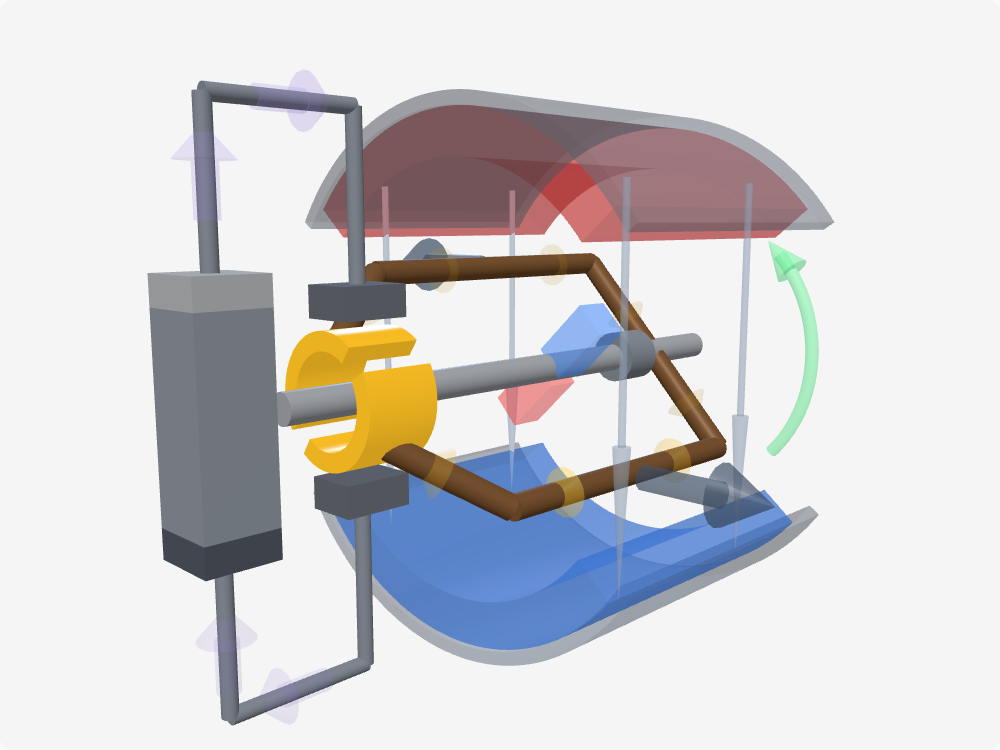
Current enters at the brushes
-
01
Current enters at the brushes
Current leaves the battery, runs up the lead and into a carbon brush. The brush does not move; the copper it presses on is bolted to the shaft and turning. Rubbing contact is the only way to get current into a spinning part.
-
02
It runs round the loop
From the commutator segment the current goes out along one side of the coil, across the far end, and back along the other side to the second segment. That is the entire rotor: one loop of wire on a shaft.
-
03
The loop is a magnet
Any loop with current running round it has a magnetic field of its own, with a north face and a south face. Which face is which depends on nothing but the direction the current takes. The bar standing across the coil is that field, drawn so it has a shape you can follow.
-
04
Between two fixed magnets
Around it, the stator holds a permanent magnet each side of the gap: north above the rotor, south below it. Their field crosses the gap pointing down, through everything in it. So there are two magnets in this machine — one always there, one that exists only while current flows.
-
05
Opposite sides, opposite pushes
A current at right angles to a magnetic field gets pushed sideways. The two sides of the coil carry the same current in opposite directions, so the two pushes come out in opposite directions too: equal in strength, on opposite sides of the shaft.
-
06
Two pushes, one turn
Add those two up as forces and they cancel — nothing drags the coil sideways across the gap. Add them up as turning effort and they reinforce each other, because each one acts on its own side of the axis. That sum is torque, and it is everything the machine produces.
-
07
Lined up, no turn
Twice a revolution the coil reaches the plane where both pushes line up with the centre of the shaft. Full strength, no turning effect — which is why the green arc vanishes as you cross it. Leave the current alone past this point and those same forces would shove the coil back the way it came, until it gave up and sat still.
-
08
The split ring flips it
The gap in the commutator crosses the brushes at exactly that moment, so each brush lands on the other segment and the current through the coil reverses. Its poles swap, and the push carries on the same way round. Nothing reversed outside the brushes: the leads have carried plain DC the whole way, and the alternating current is manufactured inside the machine by two pieces of copper and the shaft they are bolted to.
Why the commutator is the whole trick
Take the commutator out and you still have a motor — for about a quarter of a turn. The coil swings until its north face is against the stator’s south, and there it sits. Push it past that point and the field pushes it straight back. What you have built is not a motor but a compass needle with extra steps.
The commutator fixes that by reversing the current at the one moment when reversing costs nothing. As the coil crosses the neutral plane the forces on its two sides point straight out from the shaft: full strength, no turning effect. That is where the gaps in the split ring are aimed. Each brush steps off one segment and onto the other, the current through the coil turns around, its north and south faces swap, and the push it was about to receive backwards arrives forwards instead.
Notice what does not reverse. Outside the brushes the current runs the same way all the time — it is a battery, it has no other setting. The alternation is manufactured inside the machine, by a mechanical switch made of two pieces of copper and the shaft they are already bolted to. That is the engineering to admire here: a rotating switch that needs no timing signal, because the thing being switched is what drives it.
What the model leaves out
One loop is the smallest motor you can explain and the worst one you could build. Watch the green torque arc in the scene: it swells, collapses to nothing twice a revolution, and swells again. A real motor would stall on the neutral plane if it ever stopped there, and it would shudder rather than pull.
Real armatures carry many coils at different angles, each on its own pair of commutator segments — a dozen or more, not two. While one coil is crossing its neutral plane the others are near their best angle, so the torque adds up to something nearly constant and the motor starts from any position. The armature is also wound on a laminated iron core, which concentrates the field into the gap and multiplies the force by far more than the extra turns alone would. The ghost bar drawn across the loop in the model is not a part either: it is a stand-in for the coil’s magnetic moment, drawn so the push has something recognisable to act on.
The brushes get glossed over too. They spark as they cross the gap, they shed carbon dust, and they set a ceiling on speed and life. The flash in the model is the cheerful version of a real and unwelcome event.
From this to the motor in an electric car
Nothing in an electric car looks like this, and everything in it works like this. The physics is unchanged — a field, a current at right angles to it, and a force — but the switching moved out of the copper and into silicon. In a brushless motor the coils are bolted to the stator where they can be cooled and never need sliding contacts, the magnets ride on the rotor, and an inverter energises the coils in sequence, thousands of times a second, using sensors or the coils’ own back-EMF to know where the rotor is.
That is the same job the commutator does here, done by transistors that never wear out and can also decide how much current to send and when. Which is why the same hardware that drives the car also brakes it: reverse the timing and the motor becomes a generator, the back-EMF pushes current back into the battery, and the car slows down. The commutator could never do that. It only ever knew one direction.
The parts
- Armature
- The rotating part that carries the current-carrying coil — here a single loop on a shaft. Also called the rotor, though on some motor types the two words refer to different things.
- Stator
- Everything that does not turn: the field magnets, the steel yoke behind them and the brushes. It provides the field the armature pushes against.
- Field magnet
- The fixed magnets whose field fills the gap. Small motors use permanent magnets; large ones use wound electromagnets, which lets you change the field and with it the speed.
- Commutator
- The split ring on the shaft. Each segment is wired to one end of the coil, and the insulating gaps are lined up so a brush crosses one exactly when the coil is where reversing does the least harm.
- Brushes
- Fixed blocks, usually carbon, that rub on the commutator to get current into a spinning part. They wear out, they spark and they limit how fast the motor can safely run.
- Torque
- Force times the distance from the axis. Two equal forces pushing opposite ways on opposite sides of a shaft cancel as forces and add as torque, which is exactly what the coil sides do.
- Neutral plane
- The position where the coil's field is lined up with the stator's. The forces on the conductors are as strong as ever, but they point straight out from the axis, so they produce no turn. It is the only safe moment to switch.
- Back-EMF
- A spinning coil in a magnetic field generates a voltage that opposes the supply. It rises with speed, which is why a motor draws a huge current at the instant of starting and far less once it is up to speed.
- Lorentz force
- The sideways push on a current in a magnetic field, at right angles to both. It is the entire output of the machine; everything else exists to keep it pointing the right way.
- Brushless DC motor
- Same physics, no commutator. The coils sit on the stator and an electronic controller switches them in sequence, using sensors or the back-EMF to know where the rotor is.